Let $f(x,y,z)=0$ be an implicit equation of the surface of the body. In order to get an implicit equation of its shadow on $x0y$ plane, it suffices to eliminate $z$ in the following system of equations :
$$\begin{cases}f(x,y,z)&=&0& \ \ \ \ (a)\\\dfrac{\partial f}{\partial z}(x,y,z)&=&0& \ \ \ \ (b)\end{cases}\tag{1}$$
This is rather intuitive. As the gradient in $(x,y,z)$, which is the normal vector to the surface at this point, has the following components :
$$\left(\dfrac{\partial f}{\partial x},\dfrac{\partial f}{\partial y},\dfrac{\partial f}{\partial z}\right),$$
imposing condition (1)b means that we select points belonging to the surface (condition (1)a) that have horizontal gradients (condition (1)b), thus are "eligible" for being projected onto a "shadow boundary" point.
For a detailed, more rigorous explanation, see the answer I made (just some days ago...) to this question : Is there a geometrical explanation for a method using critical points in a multivariable context which was in substance : "I have seen a text where they use (1), what does it mean geometricaly ?".
Remarks : 1) This method is not limited to convex bodies, but the boundaries obtained for non convex bodies may deserve interpretation...
2) This method is for smooth surfaces. When the surface is obtained by "gluing" surfaces as is the case for a cylinder with its lateral, top and bottom parts, a different treatment is possible.
Edit : You said you are interested by the particular case of the shadow of a real cylinder (the piece of a vertical cylinder between two planes $z\pm h/2$ that is rotated, then projected in any position onto the xOy plane). Here is a Matlab program that performs the operation ; I have assumed that the projection has been done on the xOy plane.
I have considered a general ellipse parametrized in the following way
$$\begin{pmatrix}x\\y\end{pmatrix}=\underbrace{\begin{pmatrix}\cos\theta&-\sin\theta\\ \sin\theta&\cos\theta\end{pmatrix}}_R\begin{pmatrix}a\cos t\\ b\sin t\end{pmatrix}$$
This program is based on the obtention of the particular values $t=t_0$ and $t=t_0+\pi$ such that the tangent vector to this ellipse
$$\begin{pmatrix}x'\\y'\end{pmatrix}=\begin{pmatrix}\cos\theta&-\sin\theta\\ \sin\theta&\cos\theta\end{pmatrix}\begin{pmatrix}-a\sin t\\ b\cos t\end{pmatrix}$$
is proportional to the displacement vector , i.e., has the same polar angle (line 6 in the program).
clear all;close all;hold on;grid on;axis equal;
a=rand;b=rand;
th=rand*pi/2;c=cos(th);s=sin(th);R=[c,-s;s,c];% (fixed) rotation matrix
sg=2*(rand>0.5)-1;dx=3*rand;dy=3*rand;% shift components in x and y
plot([-sg*dx,sg*dx],[-dy,dy],'r');% axis
V=diag([1/a,1/b])*inv(R)*[dx;dy];% tgt vector prop. to transl. vector
t0=atan(-V(1)/V(2));% decision value of parameter t for transl. or not
if t0<0;t0=pi+t0;end;% transform any neg. angle into its suppl.
t=0:pi/200:2*pi;
si=ones(1,length(t)).*(t>t0).*(t<(pi+t0));si=1-2*si;% if  t0<t<t0+pi first half ellipse
V=R*[a*cos(t);b*sin(t)];% rotated ellipse by angle th
plot(sg*(V(1,:)-dx*si),V(2,:)-dy*si,'g');% hidden contour
plot(sg*(V(1,:)+dx*si),V(2,:)+dy*si,'b');% visible contour
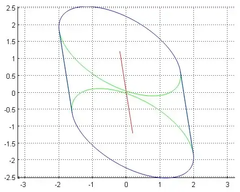
Fig. 1 : Visible contour is blue.

I have another thought: The above equations are similar to finding the silhouette of the face of the solid along the projection direction. So we have N*L=0, where N is the normal of the face and L is the projection direction vector, in this case, L being (0,0,1).
But how do I deal with special cases when the body has planar faces? An example is that when a tilted cylinder is projected onto the XY plane. The bottom/top face contribute to the profile of the projection but I cannot find these by using the silhouette function
– Steph Fong Feb 02 '19 at 02:38